The PoolShark project was completed by Team 16 of ECE 4950 (Integrated Design I) in Fall 2025 at Clemson University. I worked on this team alongside John Walker Bolding, David Bootle, William McGlone, and Blake Morgan. Our team was tasked with designing an automated mini-billiards system capable of detecting ball positions and striking a ball from one end of the table into a selected pocket on the opposite side.
The final design integrates key engineering fields including Linear Control Systems, Computer Vision, and Mechanical Design to achieve a fully automated aiming and firing sequence.
View the PoolShark GitHub Repository

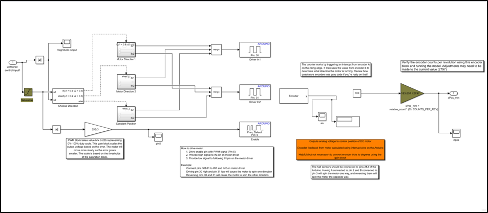
This project utilized Linear Control Systems to safely operate and execute the motor movements involved with the system. The main utilization of this was in the DC Motor Model. The DC Motor Model was controlled with a closed-feedback loop that used a PID tuning and a sum block to subtract the expected motor position from the detected motor position. The DC Motor had a hall sensor built into it, this was responsible for returning the detected position to the Simulink for further feedback loop continuation until the motor approximated to final position.
This project also utilized Simulink for the digital writes to the servo motor and solenoid. The servo motor was pushed a PWM signal to rotate the pointer to the desired aim angle. The solenoid control block issued a simple digital high/low command to trigger the shot mechanism.
The combination of these two control elements formed the full Simulink pipeline for the PoolShark project. The DC motor positioned the cue along the gantry X-axis, then the servo adjusted to its commanded position, and after a brief delay the solenoid fired. This sequencing ensured a predictable, repeatable, and safe motion, allowing the system to translate X position in millimeters and desired angle into physical actions
Primary Contributors: Camren Khoury, John Walker Bolding
DC Motor Control Block
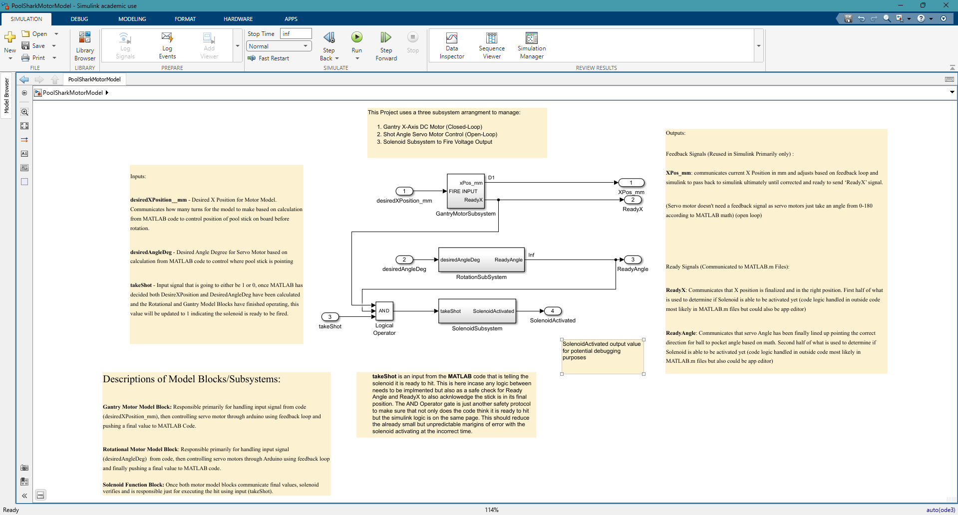
DC Motor, Servo, and Solenoid Subsystems
The circuit diagram to the left shows how the DC motor, solenoid, and servo interface with the Arduino Mega 2560 microcontroller provided with the lab through dedicated power and switching components. Each subsystem uses different hardware requirements, and the circuit is broken into three functional blocks similar to the associated Simulink model blocks above.
The DC motor subsystem uses a motor driver to safely interface the motor with the Arduino, due to differences in voltage and current requirements between the two. The DC motor is connected to a 12V DC Power supply since the microcontroller can not supply a voltage over 5V safely. The arduino provides PWM and directional signals to the motor driver, allowing control of both motor speed and rotational direction. The servo subsystem uses a standard PWM control signal from the Arduino digital write to set its rotational angle. It receives its own 5V and ground lines and the internal electronics will interpret the PWM commands and self-adjust the position until the servo essentially fights to the desired position. The solenoid subsystem requires a N-channel MOSFET which acts as a high-current switch to power the solenoid on command. The Arduino is responsible for driving the MOSFET gate through the 47 ohm resistor, which slightly removes overcurrent and reduces noise. The 10k ohm resistor is placed on the MOSFET gate to ensure the solenoid remains off during startup or if the control pin is undecided and currently neither driving 1 or 0.
Primary Contributor: Blake Morgan
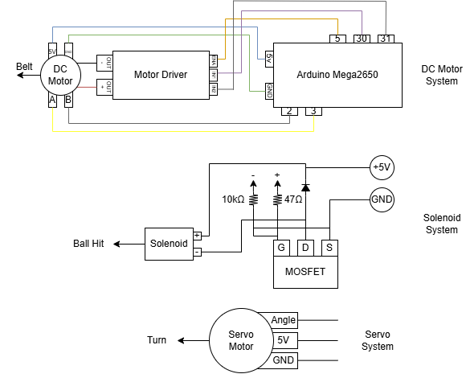
Pool Shark Circuit Diagram
The vision system relies on multiple coordinated computer-vision elements including homography correction, HSV color masking, and object morphology and reconstruction. The combination of these elements takes a raw out-of-position webcam frame and converts it into a top-down bird's-eye representation of the table with specific billiard balls and their locations located.
The homography transformation converts the angled webcam image into a proportionate bird's-eye view, top-down representation of the pool table. The camera is mounted off to the side in the initial gantry design, which became a limitation when it came to computer vision, thus homography was implemented to give a better view of the table and to account for perspective distortion. From the initial perspective objects that are located further from the camera, appear smaller and have less pixels associated per mm in real life, and the table edges are skewed. The homography corrects this by mapping the four corners of the real table to a rectangular coordinate system during an early calibration step.
The software defines a target rectangle whose dimensions match the actual table size and resolution desired for processing. The MATLAB code computes a projective transform matrix with fitgeotrans, which mathematically describes how every point in the original image maps to the now uniform top-down view.
Once the frame is calculated, the frame is remapped using the MATLAB iwarp function. This step reconstructs a new image where straight lines remain straight and distances are consistent across the table. The resulting image becomes the new frame for calculations for color detection, morphology, and centroid placement allowing for accurate angle calculations and distance placement.
Primary Contributors: William McGlone, Camren Khoury
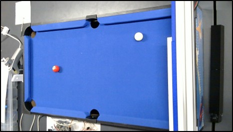
Pre Homography Example
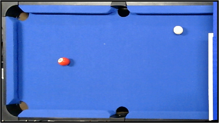
Post Homography Example
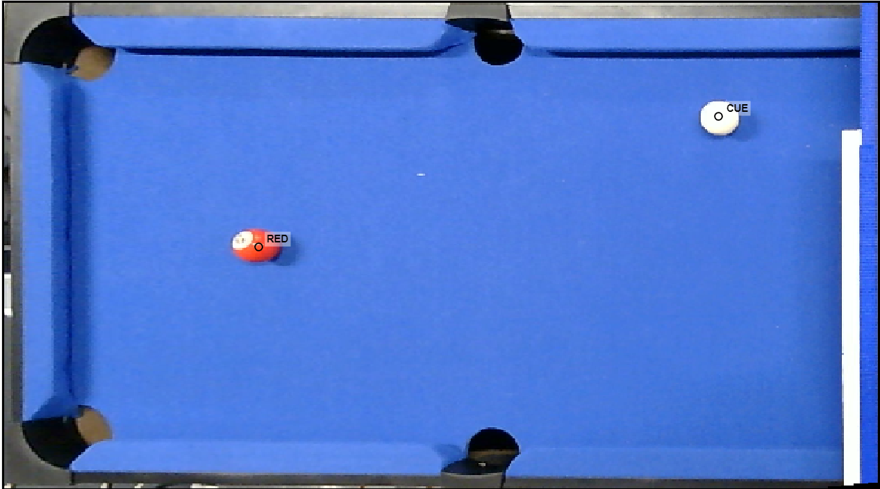
Post-Homography Example with Detection
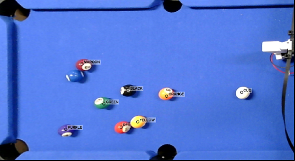
Eight Ball Color Detection (Blue Disabled)
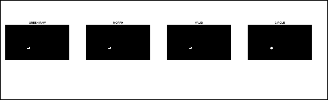
Morphology Example (Green)
The image detection system analyzes the post-homography camera frame to identify each billiard ball on the table. Homography correction ensures a consistent top-down coordinate frame, which provides a reliable basis for color detection and centroid extraction. The system then processes this corrected frame through several stages that identify ball colors, refine shapes, and verify geometric consistency. The overall goal is to produce a clean and accurate set of ball positions that can be passed to later components such as shot-geometry calculations and motor control.
Color identification is performed in the HSV color space, which offers more stable segmentation under varying lighting compared to traditional RGB thresholding. Each ball color has a defined hue, saturation, and value range that is used to generate a raw mask for that specific color. The system cycles through every color class and extracts candidate regions that match the expected HSV profile. This is helpful when objects in the frame may share similar shades but differ in saturation or brightness. After initial thresholding, geometric checks such as size, aspect ratio, and boundary location are applied to reject false positives. This stage produces filtered color masks that isolate the most likely regions corresponding to actual billiard balls.
After generating the color masks, the system applies morphological filtering to remove noise and reconstruct cleaner ball shapes. Morphology eliminates speckles, fills small gaps, and helps distinguish between objects that share a similar color but do not match the expected size or shape of a billiard ball. Circular reconstruction is then used to rebuild each ball into a more uniform circular region. This helps maintain consistent centroid placement even when the real ball contains white number patches that break the color mask or when lighting distorts the ball edge. The final output is a structured list of detected balls that includes color, centroid, area, and other properties required for accurate shot-geometry computation.
Primary Contributor: Camren Khoury
The project uses a two-part user interface design to allow for a visually pleasing user entrance design, but also a basic, sleek, high-performance control page during machine operation. When the program is initially run, the PoolShark entrance page opens. This page displays custom graphics such as a Clemson paw pool table, a cartoon shark, and video game-like loading graphics. This page was primarily created using MATLAB's App Designer, but was also conditionally modified in the MATLAB code.
Once the user clicks the "Play Game" button, the calibration stage starts to gather user-input corners of the pool table to later be used to compute the homography of the image. This calibration step then leads to the PoolShark control page, which shows the most recent active frame and gives the user input options for which ball to hit and which pocket to hit it into. From this point on, the system is fully automated, only requiring user input when there is a change in the desired ball or pocket.
Future plans for this design element include replacing the drop-down menus with cartoon billiard balls and cartoon pockets that the user could click to choose their desired shot. Another potential design improvement would be to actively display the centroid values to the user in the camera feed that is currently being displayed.
Primary Contributor: Camren Khoury
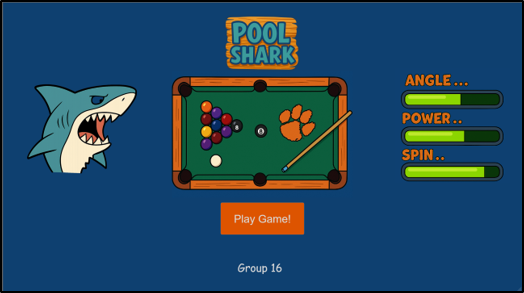
Pool Shark Entrance Page
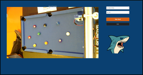
Pool Shark Control Page
The mechanical design of the PoolShark system provides the physical foundation that supports the computer vision hardware, gantry motion system, and firing assembly. An aluminum extrusion chassis was used as the primary structural framework due to its rigidity, modularity, and compatibility with off-the-shelf mounting hardware. This chassis allowed the team to securely integrate multiple subsystems while maintaining alignment and stability during operation.
Lateral positioning of the firing assembly is achieved through a belt-driven gantry system powered by a DC motor. Timing belts and pulleys convert rotational motion into smooth, controllable linear motion across the width of the pool table. Custom brackets and mounting plates were designed to interface the motor and belt system with the aluminum frame, enabling precise positioning while minimizing vibration and mechanical noise.
The firing assembly integrates a servo motor for angular aiming and a solenoid for delivering the impulse required to strike the cue ball. These components are housed in custom 3D-printed mounts that prioritize rigidity and compactness to reduce mechanical play. By rigidly coupling the servo and solenoid to the gantry system, the mechanical design ensures consistent shot alignment and repeatable firing behavior during automated operation.
Primary Contributors: David Bootle, William McGlone, John Walker Bolding
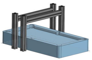
Gantry CAD Model
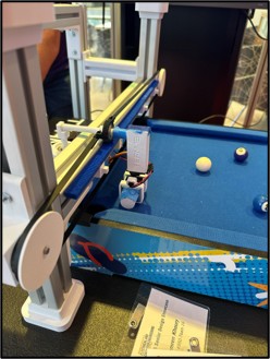
Final gantry with belt-driven motion
The shot-geometry module computes the final two values needed for the Simulink Motor Model to initiate movement. These two values are the rotation angle of the servo motor pointing the cue and the X-position the cue needs to be at on the table via the gantry carriage. These values are calculated directly from the top-down coordinate frame produced by the homography transformation. The function first identifies the cue ball and the selected target ball from the image detection structure that is passed from the detectBallsHSV.m pipeline. If either ball is not available, the computation defaults to just potting the cue ball.
Pocket selection determines the desired travel direction of the target ball, which in this project is always away from the gantry. Each pocket is represented by fixed pixel-coordinate locations on the warped table image. Once the pocket location is known, the geometry between the target ball and pocket is used to compute the "ghost ball" location, which is the point where the cue ball must make contact to send the target into the selected pocket. The ghost ball is offset from the target ball by the estimated cue radius, which is calculated from the ball's bounding box.
After the ghost ball location is identified, the function computes the vector from the cue ball to the ghost point and converts it into a servo rotation angle within the 0 to 180 degree range required by the pointer assembly. The X-axis carriage placement is then determined by mapping the ghost ball coordinates from pixel space into real world millimeters based on the calibrated table height and the usable travel distance of the DC motor driven gantry. The function finally passes the calculated servo angle, X-position, and a constant maximum solenoid power to the poolSharkExecuteShot MATLAB file which is responsible for communicating with the Simulink Motor Model.
Primary Contributor: John Walker Bolding
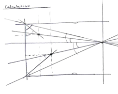
Shot Geometry Sketch
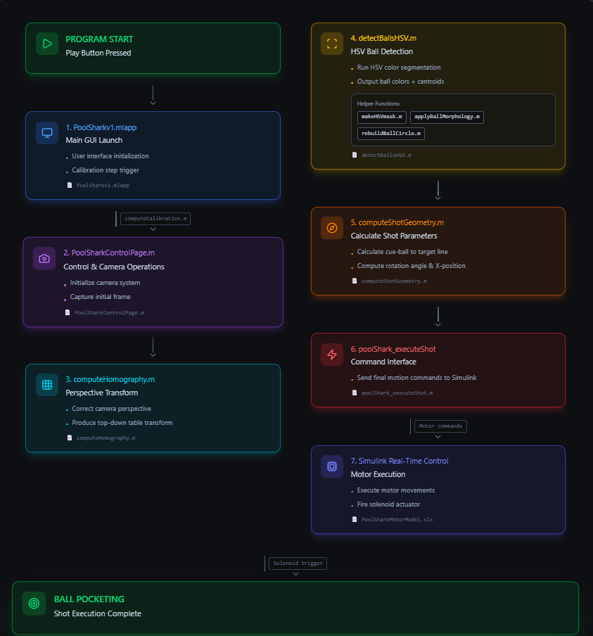
Operations Flow Chart Diagram made with Figma
Minimal Group Website: https://sites.google.com/g.clemson.edu/ece4950group16f25/final-project?authuser=0